Mechanical Presses
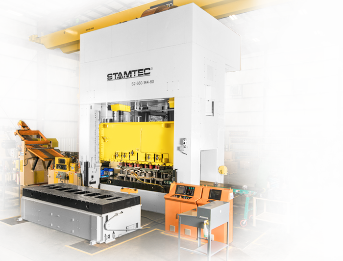
Stamtec’s Mechanical Presses (a.k.a. OBG, OBS, OBI, or C-frame) undergo finite element analysis prior to manufacturing to ensure proper design, superior strength and maximum resistance to deflection
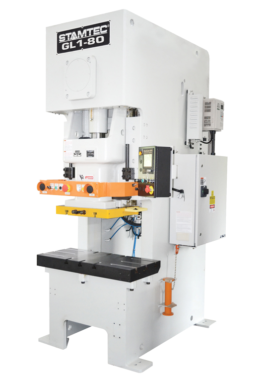
The Stamtec GL1 one-point gap frame press (a.k.a. OBG, OBS, OBI, or C-frame) with link motion drive technology is designed for stamping small parts that require deeper or more complex forming, at high single-stroking rates or in continuous mode, using either blanks or coil stock.
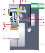
With a link motion press, the slide velocity decreases by up to 40 percent during the working portion of the stroke so the material flows more effectively while the non-working portion of the stroke increases by an offsetting amount to maintain high production rates. The results are better quality parts produced at higher production rates. In addition, the slower speed of the working stroke in the GL1 stamping press reduces die impact, punch penetration, snap-through, noise and vibration, thereby increasing machine and die life.
TONNAGE RANGE: 88-220
DELIVERY TIME: some models in stock or with quick delivery
Stamtec presses can be customized to meet a wider range of SPM, stroke, rating point (BDC), bed and other specifications and dimensions.
Review the specs and advantages of our GL1 Link Motion Series gap frame press below, and then contact us by calling 931-393-5050 or submitting this simple form for assistance in identifying the steel stamping machines you need.
| MODEL GL1-80 SPECIFICATIONS | |||
|---|---|---|---|
| Type | B | D | |
| Capacity | US Tons | 88 | 88 |
| Metric Tons | 80 | 80 | |
| Rated tonnage point | in. | 0.2 | 0.2 |
| mm | 5 | 5 | |
| Stroke length | in. | 3.94 | 6.3 |
| mm | 100 | 160 | |
| Speed | SPM | 55 ~ 110 | 40 ~ 75 |
| Die height (S.D.A.U.) | in. | 11.81 | 12.99 |
| mm | 300 | 330 | |
| Maximum upper die weight | lbs | 1212.54 | 1212.54 |
| kg | 550 | 550 | |
| Slide adjustment | in. | 3.15 | 3.15 |
| mm | 80 | 80 | |
| Bolster area (L-R X F-B) | in. | 39.37 x 18.11 | 39.37 x 23.62 |
| mm | 1000 x 460 | 1000 x 600 | |
| Bolster thickness | in. | 3.94 | 3.94 |
| mm | 100 | 100 | |
| Slide area (L-R x F-B) | in. | 22.05 x 18.11 | 22.05 x 18.11 |
| mm | 560 x 460 | 560 x 460 | |
| Main motor | Fixed Speed | 10 HP x 4 P | 10 HP x 4 P |
| Variable Speed | VS 10 HP x 4 P | VS 10 HP x 4 P | |
| Slide adjusting motor | kw x P | 0.4 x 4 | 0.4 x 4 |
| DIE CUSHION DEVICE | |||
| Type | B | D | |
| Capacity | US Tons | 6 | 6 |
| Metric Tons | 6.3 | 6.3 | |
| Pad area | in. | 16.14 x 10.24 | 16.14 x 10.24 |
| mm | 410 x 260 | 410 x 260 | |
| Stroke | in. | 2.76 | 2.76 |
| mm | 70 | 70 | |
| DIMENSIONS | |||
| Type | B | D | |
| Machine width (L.R.) | in. | 32.68 | 32.68 |
| mm | 830 | 830 | |
| Machine depth (F.B.) | in. | 68.31 | 73.03 |
| mm | 1735 | 1855 | |
| Machine height (H) | in. | 111.02 | 113.39 |
| mm | 2820 | 2880 | |
| MODEL GL1-110 SPECIFICATIONS | |||
|---|---|---|---|
| Type | B | D | |
| Capacity | US Tons | 121 | 121 |
| Metric Tons | 110 | 110 | |
| Rated tonnage point | in. | 0.2 | 0.2 |
| mm | 5 | 5 | |
| Stroke length | in. | 3.94 | 7.09 |
| mm | 110 | 180 | |
| Speed | SPM | 50 ~ 100 | 30 ~ 65 |
| Die height (S.D.A.U.) | in. | 12.6 | 13.78 |
| mm | 320 | 350 | |
| Maximum upper die weight | lbs | 1366.87 | 1366.87 |
| kg | 620 | 620 | |
| Slide adjustment | in. | 3.54 | 3.54 |
| mm | 90 | 90 | |
| Bolster area (L-R X F-B) | in. | 45.28 x 20.47 | 45.28 x 26.77 |
| mm | 1150 x 520 | 1150 x 680 | |
| Bolster thickness | in. | 4.72 | 4.72 |
| mm | 120 | 120 | |
| Slide area (L-R x F-B) | in. | 25.59 x 20.47 | 25.59 x 20.47 |
| mm | 650 x 520 | 650 x 520 | |
| Main motor | Fixed Speed | 15 HP x 4 P | 15 HP x 4 P |
| Variable Speed | VS 15 HP x 4 P | VS 15 HP x 4 p | |
| Slide adjusting motor | kw x P | 0.4 x 4 | 0.4 x 4 |
| DIE CUSHION DEVICE | |||
| Type | B | D | |
| Capacity | US Tons | 8 | 8 |
| Metric Tons | 8 | 8 | |
| Pad area | in. | 19.69 x 11.81 | 19.69 x 11.81 |
| mm | 500 x 300 | 500 x 300 | |
| Stroke | in. | 3.15 | 3.15 |
| mm | 80 | 80 | |
| DIMENSIONS | |||
| Type | B | D | |
| Machine width (L.R.) | in. | 38.19 | 38.19 |
| mm | 970 | 970 | |
| Machine depth (F.B.) | in. | 82.87 | 83.27 |
| mm | 2105 | 2115 | |
| Machine height (H) | in. | 117.32 | 119.88 |
| mm | 2980 | 3045 | |
| MODEL GL1-160 SPECIFICATIONS | |||
|---|---|---|---|
| Type | B | D | |
| Capacity | US Tons | 176 | 176 |
| Metric Tons | 160 | 160 | |
| Rated tonnage point | in. | 0.24 | 0.24 |
| mm | 6 | 6 | |
| Stroke length | in. | 5.12 | 7.87 |
| mm | 130 | 200 | |
| Speed | SPM | 40 ~ 85 | 25 ~ 50 |
| Die height (S.D.A.U.) | in. | 13.78 | 75.72 |
| mm | 350 | 450 | |
| Maximum upper die weight | lbs | 1543.24 | 1543.24 |
| kg | 700 | 700 | |
| Slide adjustment | in. | 3.94 | 3.94 |
| mm | 100 | 100 | |
| Bolster area (L-R X F-B) | in. | 49.21 x 23.62 | 49.21 x 29.92 |
| mm | 1250 x 600 | 1250 x 760 | |
| Bolster thickness | in. | 5.91 | 5.91 |
| mm | 150 | 150 | |
| Slide area (L-R x F-B) | in. | 27.56 x 22.83 | 27.56 x 22.83 |
| mm | 700 x 580 | 700 x 580 | |
| Main motor | Fixed Speed | 15 HP x 4 P | 15 HP x 4 P |
| Variable Speed | VS 15 HP x 4 P | VS 15 HP x 4 P | |
| Slide adjusting motor | kw x P | 0.5 x 4 | 0.5 x 4 |
| DIE CUSHION DEVICE | |||
| Type | B | D | |
| Capacity | US Tons | 11 | 11 |
| Metric Tons | 10 | 10 | |
| Pad area | in. | 21.26 x 13.77 | 21.26 x 13.77 |
| mm | 540 x 350 | 540 x 350 | |
| Stroke | in. | 3.15 | 3.15 |
| mm | 80 | 80 | |
| DIMENSIONS | |||
| Type | B | D | |
| Machine width (L.R.) | in. | 42.13 | 42.13 |
| mm | 1070 | 1070 | |
| Machine depth (F.B.) | in. | 84.65 | 90.35 |
| mm | 2150 | 2295 | |
| Machine height (H) | in. | 130.32 | 133.66 |
| mm | 3310 | 3395 | |
| MODEL GL1-200 SPECIFICATIONS | |||
|---|---|---|---|
| Type | B | D | |
| Capacity | US Tons | 220 | 220 |
| Metric Tons | 200 | 200 | |
| Rated tonnage point | in. | 0.24 | 0.24 |
| mm | 6 | 6 | |
| Stroke length | in. | 5.91 | 7.87 |
| mm | 150 | 200 | |
| Speed | SPM | 35 ~ 70 | 20 ~ 45 |
| Die height (S.D.A.U.) | in. | 16.14 | 17.72 |
| mm | 410 | 450 | |
| Maximum upper die weight | lbs | 1763.7 | 1763.7 |
| kg | 800 | 800 | |
| Slide adjustment | in. | 4.33 | 4.33 |
| mm | 110 | 110 | |
| Bolster area (L-R X F-B) | in. | 55.12 x 26.77 | 55.12 x 32.28 |
| mm | 1400 x 680 | 1400 x 820 | |
| Bolster thickness | in. | 6.69 | 6.69 |
| mm | 170 | 170 | |
| Slide area (L-R x F-B) | in. | 33.47 x 25.59 | 33.47 x 25.59 |
| mm | 850 x 650 | 850 x 650 | |
| Main motor | Fixed speed | 15 HP x 4 P | 15 HP x 4 P |
| Variable Speed | VS 20 HP x 4 P | VS 20 HP x 4 P | |
| Slide adjusting motor | kW x P | 0.75 x 4 | 0.75 x 4 |
| DIE CUSHION DEVICE | |||
| Type | B | D | |
| Capacity | US Tons | 15 | 15 |
| Metric Tons | 14 | 14 | |
| Pad area | in. | 25.20 x 18.50 | 25.20 x 18.50 |
| mm | 640 x 470 | 640 x 470 | |
| Stroke | in. | 3.94 | 3.94 |
| mm | 100 | 100 | |
| DIMENSIONS | |||
| Type | B | D | |
| Machine width (L.R.) | in. | 50.2 | 50.2 |
| mm | 1275 | 1275 | |
| Machine depth (F.B.) | in. | 94.49 | 100.39 |
| mm | 2400 | 2550 | |
| Machine height (H) | in. | 145.67 | 151.77 |
| mm | 3700 | 3855 | |
Slower speed of the working stroke reduces die impact, punch penetration, snap-through, noise and vibration, thereby increasing machine and die life.
Standard link motion drive technology in this mechanical stamping machine facilitates production of better quality parts at higher production rates.
Productivity can be increased by 20 to 40 percent over conventional presses working at the same forming velocity.